

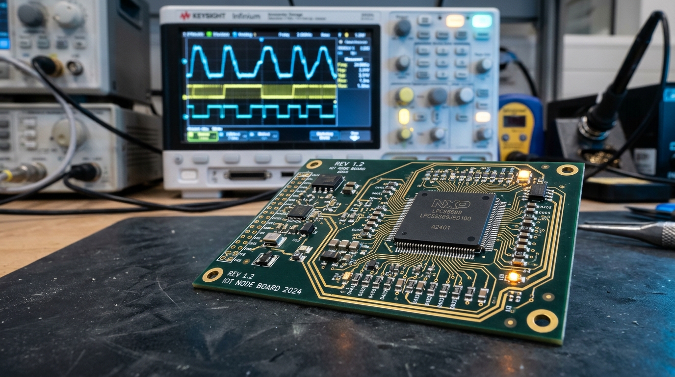
Core Foundations of Electronic Engineering Technology.
Electronic engineering technology builds physical hardware from circuit ideas. Teams design fast embedded systems. They test multi-layer circuit boards. Electronic engineering technology links schematic plans to factory lines. Teams combine microcontrollers, sensors, and power chips. They track timing faults on lab benches. Reading our guide on integrated device technology helps teams pick low-jitter clock chips. Sound design cuts board flaws and boosts output. Labs test each run.
Key Engineering Targets.
- Trace Control: Hold 50-ohm trace impedance.
- Firmware Speed: Run real-time loops on bare silicon.
- Test Loops: Build automated SCPI test script racks.
- Noise Limits: Shield circuits to pass EMC radiation rules.
The Shift from Theory to Hands-On Production.
Science studies math and field equations. In contrast, applied electronic engineering focuses on real build steps. Techs design physical boards. They solder small surface parts. They flash code onto microcontrollers. They test prototypes on lab benches. Labs test real boards. Techs fix line faults.
Real hardware must endure tough plant floors. Heat, shock, and power surges strain every trace. Careful bench tests ensure that boards pass industry rules. Teams stress parts under high heat to stop field breakdowns. Good tests save cash.
Embedded Systems and Microcontroller Hardware.
Smart products run on embedded microcontrollers. Small chips run real-time code on ARM or RISC-V cores. Microcontrollers read analog sensors through built-in ADC pins. They process inputs with fast timers. They drive motors with pulse-width modulation.
Techs write bare-metal C code. They handle hardware interrupts with zero dropped bytes. Reviewing chip industry manufacturing explains silicon die yields and wafer supply limits. Solid firmware and good silicon build durable gear. Fast chips run cool.
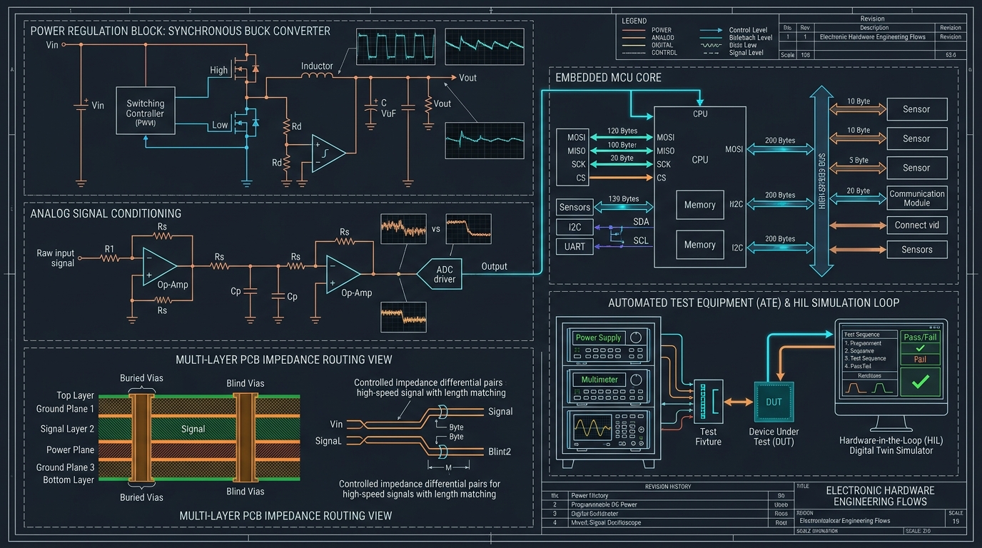
Figure 1.0: Complete electronic engineering system architecture showing sensor inputs, microcontroller signal conditioning, power management, and automated SCPI test loop validation.
Analog Signal Chains and Sensor Conditioning.
Real-world signals are weak and noisy. Sensors output tiny millivolt signals from strain gauges. Electronic engineering technology uses clean analog front ends to boost weak signals. Techs filter raw inputs.
Operational Amplifier Filters and Buffer Stages.
Raw sensor lines pick up 60 Hz hum. Instrumentation amplifiers boost tiny differential signals with high common-mode rejection. Active Sallen-Key low-pass filters strip out radio frequency noise. Clean filters cut hiss.
Op-amp buffers match line loads. They link sensors to ADC pins. Without buffer stages, the sample switch loads the sensor down. A low-noise rail-to-rail op-amp keeps analog readings sharp and true. Good buffers aid precision.
Printed Circuit Board Design and Signal Integrity.
High-speed digital traces act as transmission lines. Fast rise times create high-frequency harmonics across board traces. Electronic engineering technology sets strict layout rules for multi-layer boards. Proper trace layout prevents data loss.
Controlled Impedance and Return Current Paths.
High-speed traces require controlled impedance. Microstrip traces over solid ground planes hold 50-ohm single-ended impedance. USB and Ethernet differential pairs demand 90-ohm and 100-ohm trace spacing. Solid planes stop crosstalk.
Return currents flow directly under signal traces on ground planes. If a trace crosses a split in the plane, return loops widen. Wide return loops radiate noise and cause cross-talk. Techs keep reference planes solid under high-speed traces. Clean paths yield clean signals.
Power Distribution Networks and Decoupling.
Fast chips draw sharp current spikes. They need fast charge. Long power traces add inductance that starves silicon dies. Engineers build low-impedance power planes with decoupling capacitors. Clean power feeds each chip.
Ceramic capacitors sit right next to chip power pins. Small 0.1 uF capacitors dump instant charge during switching events. Larger bulk capacitors smooth out low-frequency voltage ripple from power supplies. Good caps drop noise.
Design for Manufacturing and Assembly Standards.
A working bench prototype is only the first step. Boards must run smoothly through high-speed pick-and-place lines. Engineers follow IPC design standards to prevent production flaws. Good rules save time.
IPC Class 2 and Class 3 Design Rules.
Consumer devices use IPC Class 2 rules. Industrial, medical, and aerospace systems demand IPC Class 3 standards. Class 3 rules demand thicker copper in plated through-holes. They require larger annular rings around vias. Strong rings stop cracks.
Boards need test points on all power nets and reset lines. Pogo pins test each board node. Techs catch flaws early. Thermal relief pads on copper pours ensure clean solder joints without cold bridges. Sound solder joints hold fast.
Academic Paths and Degree Programs in 2026.
Hardware teams need skilled staff. A sharp electronic student learns fast in bench labs. Leading electronics schools teach hands-on circuit design. Many start with an associate degree in electronics. Local colleges offer a practical aa degree in electronics. Students can also earn an electronics technology associate degree. A flexible 2 year electronics degree online helps learners save time. Labs test real boards. Techs build prototypes. They test power rails. They check clock jitter.
Four-year university electronic programs offer deep training. Students enroll in an electronic engineering degree. Earning an electronic engineering bachelors prepares grads for chip jobs. Students can also pick a bs electronics engineering track. As an electronic engineering major, students test fast microchips. These electronic majors write code in C. Top universities provide electrical and electronic engineering courses. Students build real circuit boards. They write clean firmware. They run automated test scripts. Grads find great work.
Online study offers great flexibility for adult learners. Many choose an electronics degree online while working full-time. They enroll in an online electronics engineering degree to grow. Simulation tools help them test logic gates. Taking an electronics engineering course builds math skills. Completing electronic engineering technology courses teaches board layout. Enrolling in electronics engineering technology online degree programs helps learners grow. Earning an accredited electronic degree prepares techs for high pay. Top electronics degrees lead to good pay. Hardware teams hire smart grads.
Automated Test Equipment and SCPI Scripting.
Manual testing with bench probes is too slow for factory lines. Electronic engineering technology relies on Automated Test Equipment. Engineers write Python scripts using standard SCPI commands to control bench gear. Quick scripts test boards.
Building Automated Bench Test Racks.
Automated test racks link oscilloscopes, power supplies, and digital multimeters over USB, GPIB, or Ethernet. A central test script sets supply voltages, pulses board inputs, and measures ripple. Techs verify power-on sequencing and clock jitter in seconds. Fast scans catch defects.
SCPI Automated Test Measurement Loop
import pyvisa
import time

rm = pyvisa.ResourceManager()
dmm = rm.open_resource("TCPIP::192.168.1.101::INSTR")
psu = rm.open_resource("TCPIP::192.168.1.102::INSTR")

psu.write(":VOLT 3.3")
psu.write(":OUTP ON")
time.sleep(0.05)

voltage = float(dmm.query(":MEAS:VOLT:DC?"))
print(f"Measured 3.3V Rail: {voltage:.4f} V")

if 3.20 <= voltage <= 3.40:
    print("PASS: Rail within 3% tolerance.")
else:
    print("FAIL: Out of spec rail detected.")
Code 1.0: Python PyVISA test script measuring rail voltage under load.
Empirical Benchmarks for Embedded Bus Protocols.
Picking the right bus protocol impacts system throughput and board complexity. Engineers weigh speed against trace count and noise immunity. Bench data guides design choices.
| Bus Protocol | Max Data Rate | Wire Count | Max Distance | Best Application |
|---|---|---|---|---|
| UART | 921.6 kbps | 2 (TX, RX) | < 15 m | Debug consoles and modems |
| I2C | 3.4 Mbps | 2 (SDA, SCL) | < 1 m | Low-speed sensor clusters |
| SPI | 50+ Mbps | 4+ (CS per node) | < 0.3 m | Flash memory, fast displays |
| CAN Bus (FD) | 5 Mbps | 2 (CAN_H, CAN_L) | < 40 m | Automotive and noisy plant gear |
Hardware-in-the-Loop Real-Time Verification.
Testing firmware on heavy plant machines carries safety risks. Teams deploy Hardware-in-the-Loop rigs to test boards safely. The physical circuit board links to a real-time hardware simulator. Rigs run automated checks.
The simulator mimics motors, sensors, and physical loads. It feeds synthetic sensor signals into the board inputs. The board runs full production firmware. It acts as if it runs real machinery. This method uncovers timing bugs and safety faults before factory launch. Bench tests save lives.
Electromagnetic Compliance and Noise Shielding.
Hardware products must pass strict electromagnetic compatibility laws. Commercial boards must not radiate radio noise into nearby gear. They must also withstand noise from outside fields. Strict tests guard airwaves.
Engineers design noise filters directly into board schematics. Common-mode chokes block noise on cable lines. Ferrite beads soak up high-frequency ripple on power traces. Metal shield cans cover sensitive radio frequency stages to satisfy standards from the IEEE Computer Society. Clean shields block stray waves.
Engineering Verdict: Practical Paths for Electronic Design.
Mastering electronic engineering technology takes circuit theory and lab skill. Teams must test board layouts early to verify trace impedance. Solid ground planes and bypass capacitors protect signal integrity on fast buses. Good habits build great boards.
Automated test benches and Hardware-in-the-Loop rigs prove reliability before volume builds. Solid board layout, clean test code, and noise shielding deliver robust hardware across industrial fields. Lab skills yield real gains.